What is Logic Synthesis ?
Why Perform Logic Synthesis ?
1. Automatically manages many details of the design process:
• Fewer bugs
• Improves productivity
2. Abstracts the design data (HDL description) from any particular implementation technology
• Designs can be re-synthesized targeting different chip technologies;
E.g.: first implement in FPGA then later in ASIC
3. In some cases, leads to a more optimal design than could be
achieved by manual means (e.g.: logic optimization)
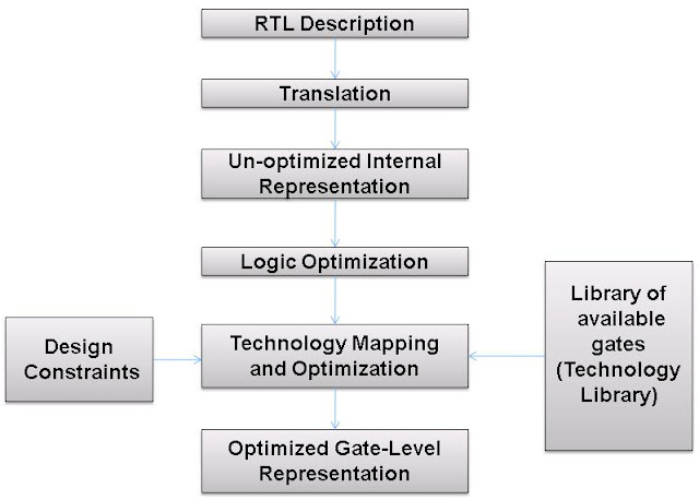
Logic Synthesis Flow : RTL TO GATES
RTL description:
Design at a high level using RTL constructs.
Translation:
Synthesis Tool convert the RTL description to un-optimized Internal representation.(Boolean form)
Un-optimized Intermediate Representation:
Represented internally by the logic synthesis tool in terms of Internal data structure.
Logic Optimization:
Logic is optimized to remove redundant logic.
Technology Mapping and Optimization:
The synthesis tool takes the internal representation and implements the representation in gates, using the cells provided in the technology library.
The synthesis tool takes the internal representation and implements the representation in gates, using the cells provided in the technology library.
library cells that can be basic gates or macro cells.
The cell description contains information about the following:
• Functionality of the cell.
• Area of the cell layout.
• Timing information about the cell.
• Power information about the cell.
Design Constraints:
1.Area:
- Designer can specify area constraint and synthesis tool will optimize for minimum area.
- Area can be optimized by having lesser number of cells and by replacing multiple cells with single cell that includes both functionality.
2. Timing:
- Designer specifies maximum delay between primary input and primary output.
I.Path between a primary input and primary output.
II.Path from any primary input to a register.
III.Path from a register to a primary output.
IV.Path from a register to another register
3. Power:
- Development of hand-held devices has led to reduction of battery size and hence low power consuming systems..
Points to note about synthesis
- For very big circuits, vendor technology libraries may yield non- optimal result.
- Translation, logic optimization and technology mapping are done internally in the logic synthesis tool and are not visible to the designer.
- Timing analyzer built into synthesis tools will have to account for interconnect delays in the total delay calculation


Useful information Crispy.
ReplyDeleteNice Blog. Thanks for sharing
ReplyDeleteExploring the Role of Semiconductors in IoT and Smart Devices
What are the common approaches to ASIC Verification?
The Impact of ASICs on the Evolution of Satellite Technology
Understanding the differences between clock gating and power gating
Understanding the Chip Design Process